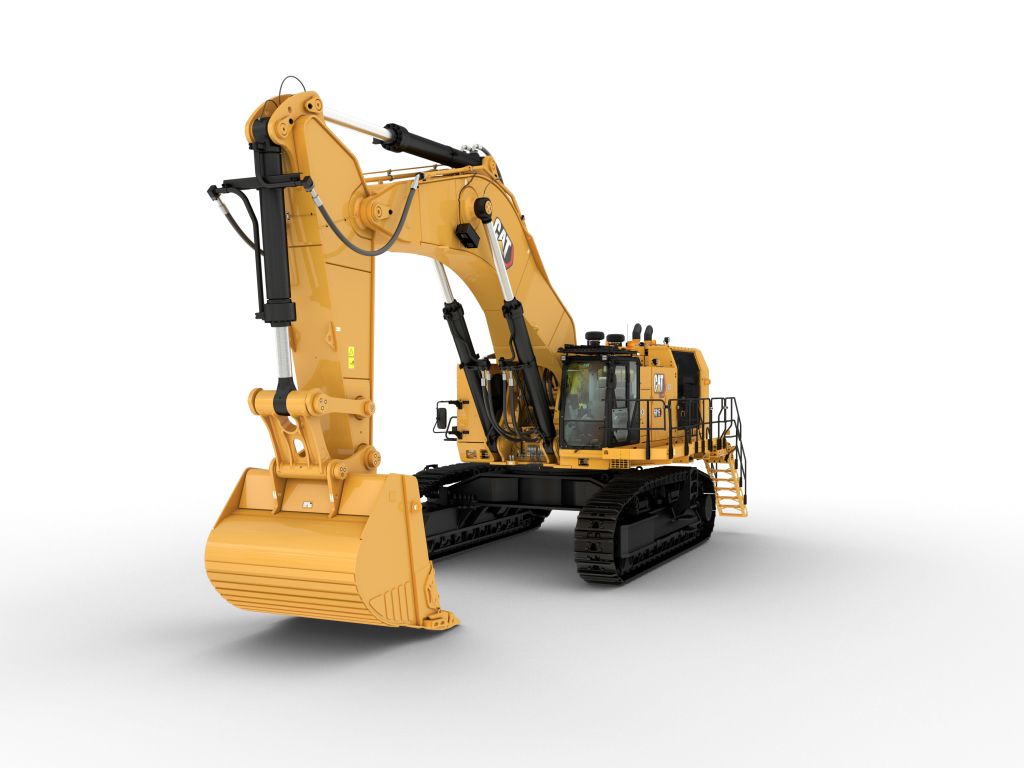
6015 Hydraulic Shovel
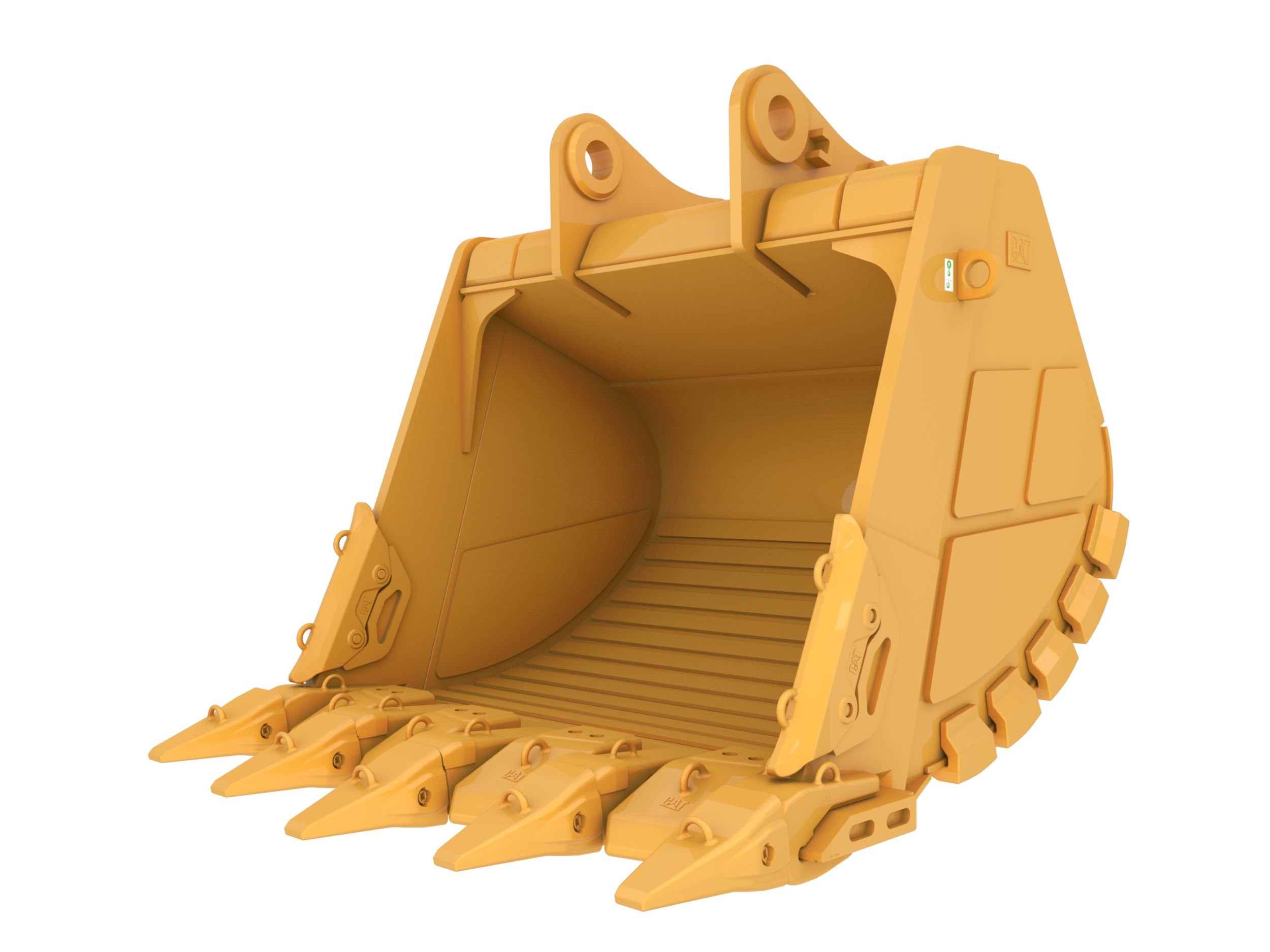
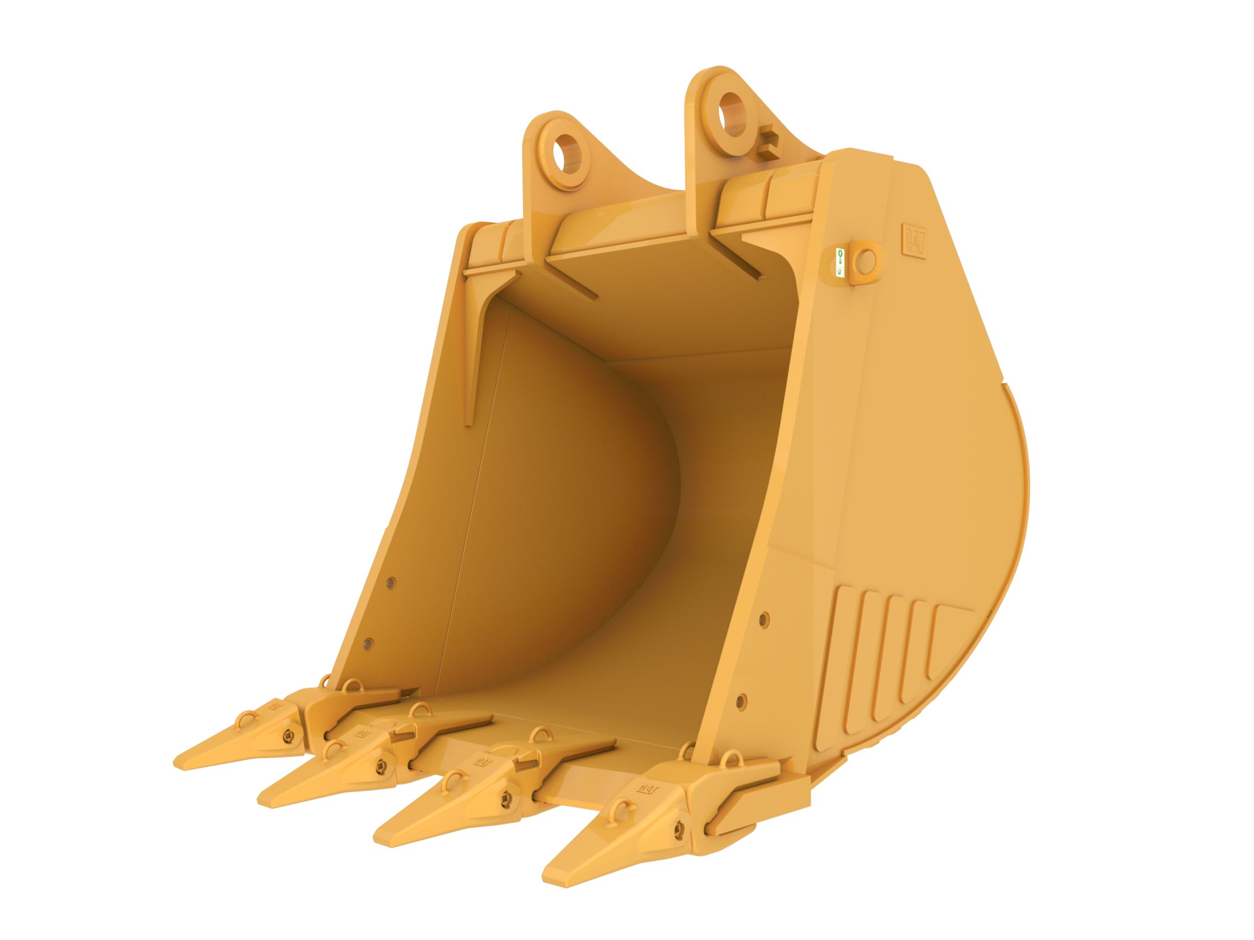
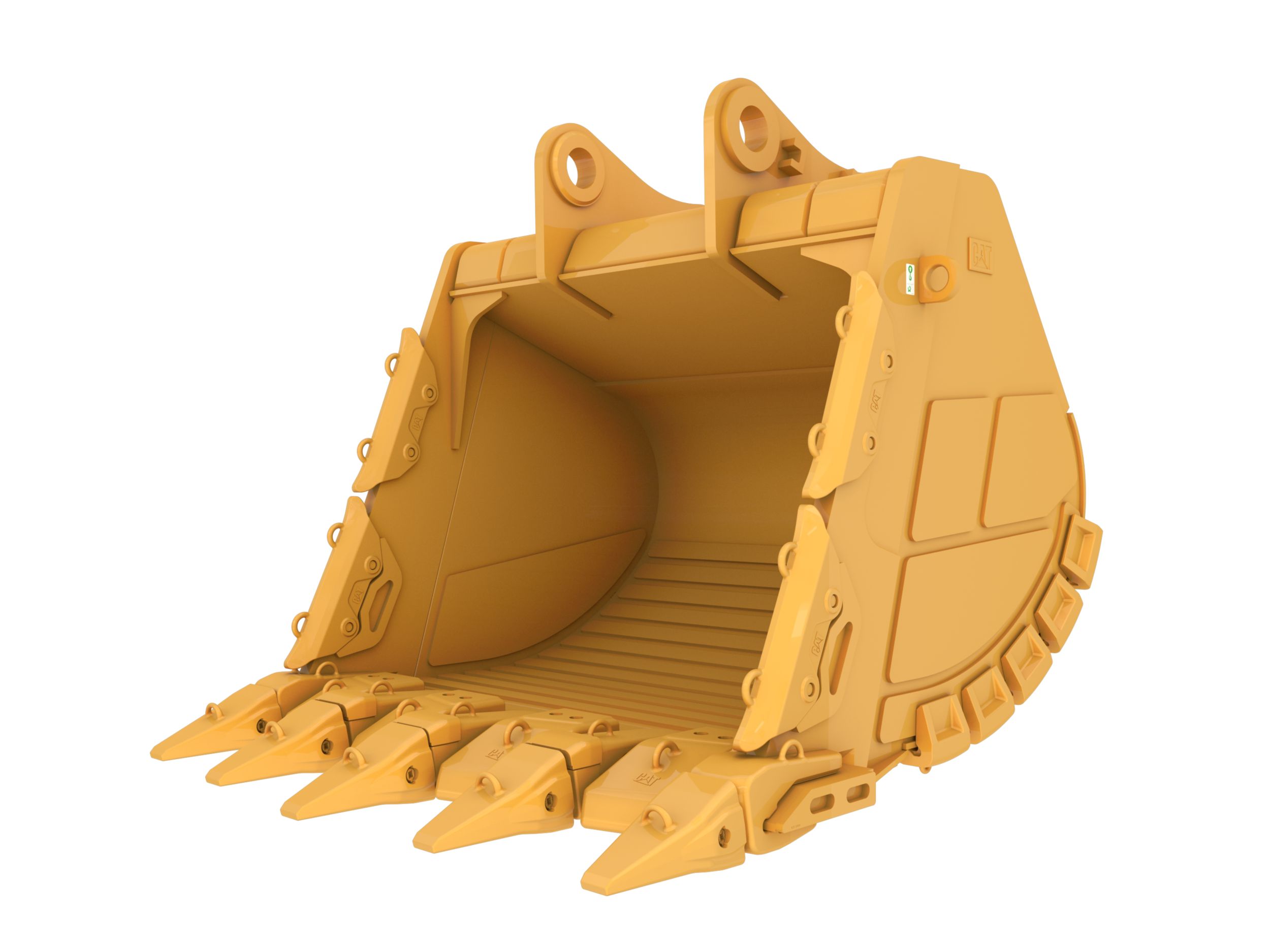
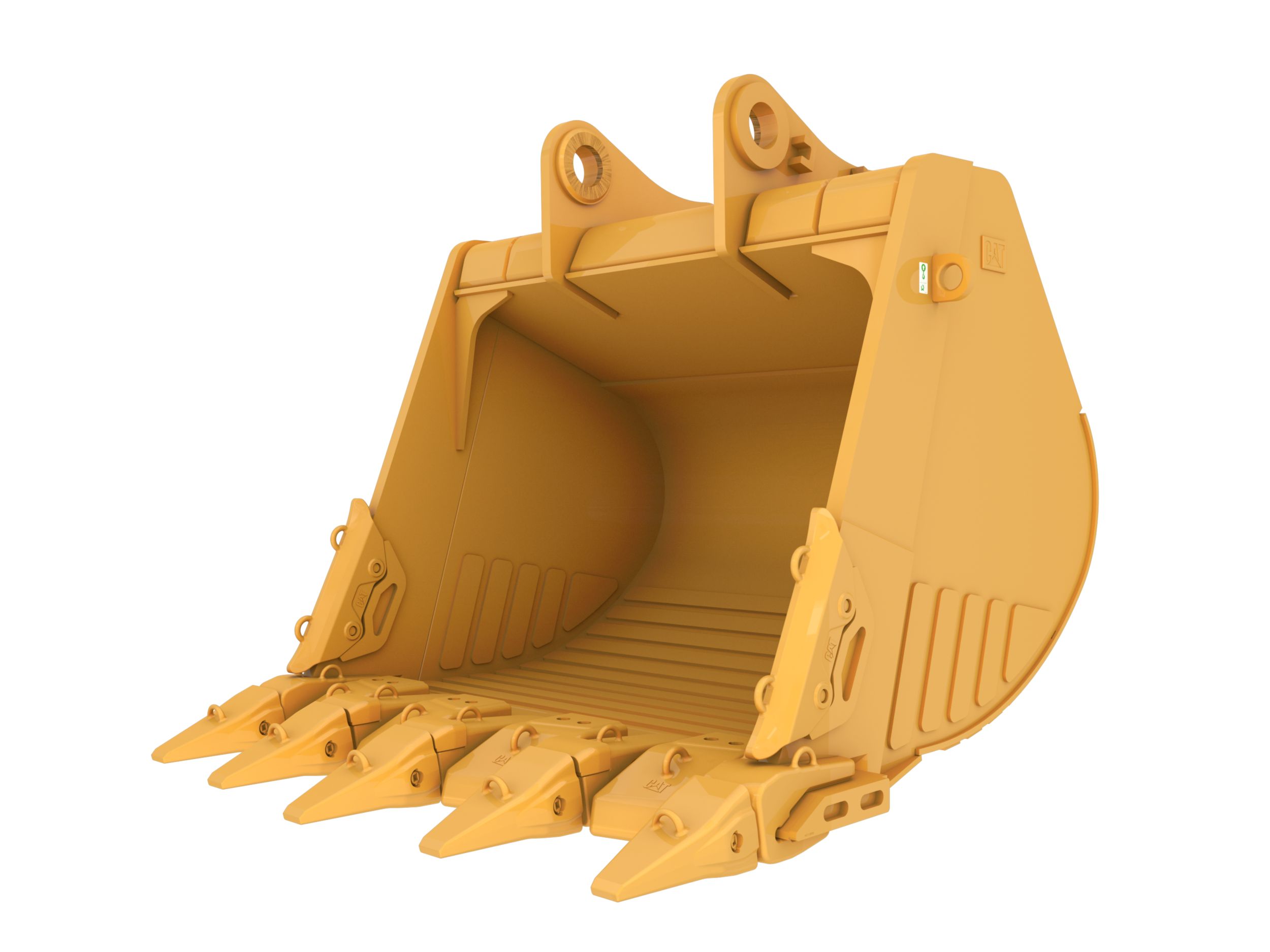
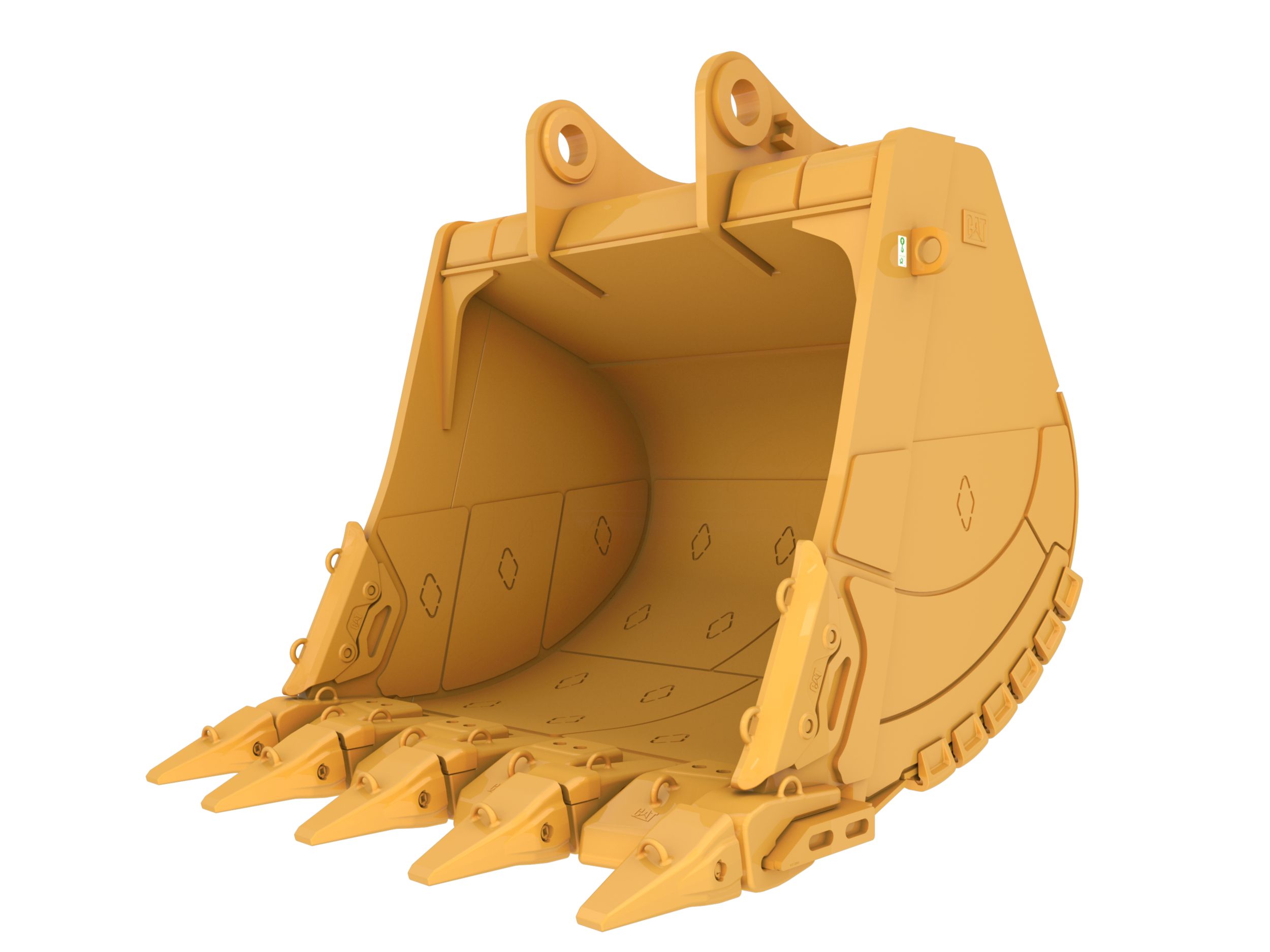
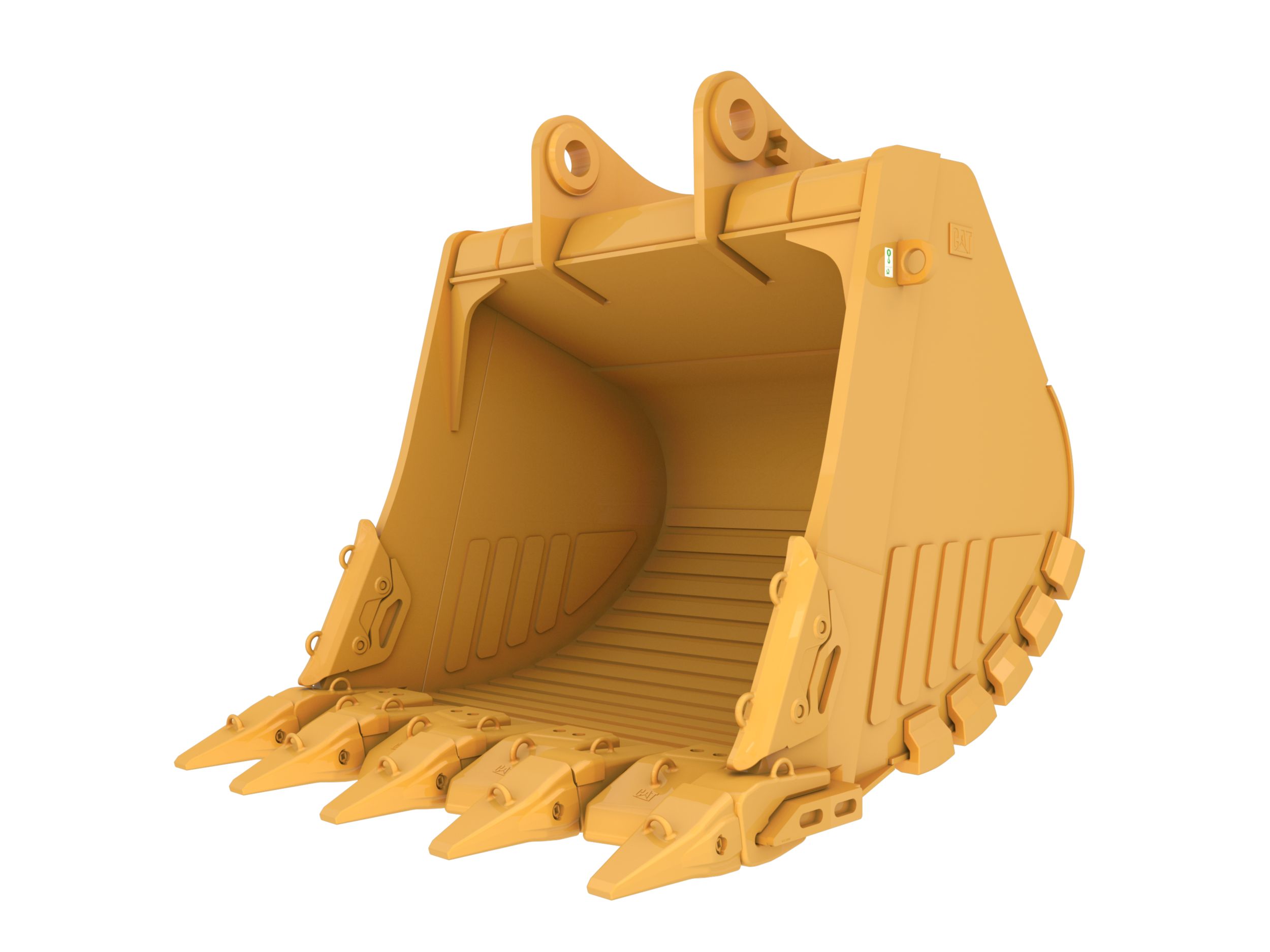
The Cat® 6015 Hydraulic Shovel lets you move more material at a lower cost, so you can achieve production targets, deliver on your commitments, meet deadlines and maximize your profitability. With class-leading tool carrying capacity, increased durability and the most powerful engine in its class, the Cat 6015 generates higher productivity and fuel efficiency than other shovels. And it’s offered with more and better options that let you match your machine to your operation — from access and cold weather packages to multiple stick and track pad options. In addition, a large range of buckets is available, giving you optimum payload and machine efficiency for your operation. And the 6015’s high tool carrying capacity gives you the ability to employ large buckets and move more in fewer cycles.